# Firmware Creation
{% hint style="success" %}
Firmware Guide - Home
1. Download the Project
2. Telescan - Guide: Extract the Donor Card Data
3. Vivado - Guide: Create Project & Fill in Telescan Data
[VS Code](https://code.visualstudio.com/sha/download?build=stable\&os=win32-x64-user)\
[Vivado](https://www.xilinx.com/support/download.html)\
[Telescan](https://drive.google.com/file/d/1siKvpYg-AMBqxR_tzayiR61kcBeuqnDn/view?usp=sharing)\
[pcileech-fpga](https://github.com/ufrisk/pcileech-fpga/archive/refs/tags/v4.15.zip)\
[Python Script](https://github.com/Rakeshmonkee/DMA/blob/main/.tlscan%20to%20.coe/telescan_to_coe.py)\
[Python 3.12](https://www.python.org/ftp/python/3.12.4/python-3.12.4-amd64.exe)
{% endhint %}
## Download the Project
Download Ulf's [pcileech-fpga](https://github.com/ufrisk/pcileech-fpga/archive/refs/tags/v4.15.zip) project, extract it and copy the folder you need for your DMA device to another location.
> \*I have a Captain DMA v4 35T, I will therefor use the `PCIeSquirrel` folder
***
Sometimes Vivado will fail to generate the project files or fail when generating the `Bitstream` copy the folder to a location that doesn't have any special characters in the folder names and isn't too long, keep it simple.
*Example*\
`C:/PCIeSquirrel`
> *This is where you'll be working on the firmware*
## **Shadow Configuration Copy**
{% hint style="success" %}
Note
*Download* [*Telescan*](https://drive.google.com/file/d/1siKvpYg-AMBqxR_tzayiR61kcBeuqnDn/view?usp=sharing)
{% endhint %}
***
**Saving the donor device with Telescan:**
To copy the configuration space from a real donor device, start [Telescan](https://drive.google.com/file/d/1siKvpYg-AMBqxR_tzayiR61kcBeuqnDn/view?usp=sharing) and go step by step as shown below.
* Click the  `save` icon in the top left corner
* Choose  `Device/Port Type Tree` and look for the device you intend to copy
* Check the box\
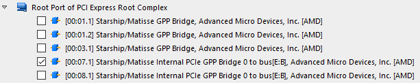
* Click  name it `Donor.tlscan` and save it to your desktop
> *example:*\
> `C:/Users/Simonrak/Desktop/Donor.tlscan`
***
{% hint style="warning" %}
Note
*Before closing Telescan we should retrieve some important values needed in Vivado later*\
\&#xNAN;*click on `Next step` below*\
ID's needed for Vivado
{% endhint %}
***
**To get the IDs needed in Vivado**
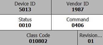
We need these values to make the DMA show up as our donor device.
* At the top of the header in your device, we need to write down:
* `Vendor ID`
* `Device ID`
* `Command`
* `Revision ID`
* `Class Code`
\
\&#xNAN;*(Write these down)*
***
{% hint style="danger" %}
***
Note
*Write these down and save them, we will need them later in Vivado*
{% endhint %}
## Bar Sizing
**Get the BAR sizing from Telescan**
The ¹`BARs` ( `Base Address Registers` ) has a specified size assigned to them from the donor device, to make our DMA firmware look like the real donor card we will also copy the `sizing`
* Click on `BAR0`\

* To the right, we can see `Base Address Register 0`
* To get the `sizing`, we need to fill the bits in the white field with `1` s\
\
(*Before*)\
\
(*After*)
* Right click on the white section in `Base Address Register 0`:
* `Write`
* `Dword at offset 010h`
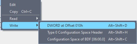
\
(*Doing this will deactivate the device, it's normal*)
Now we can see the sizing:\
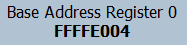\
\&#xNAN;*(Write this down)*
*If a bar ends in:*\
\&#xNAN;*`01` = IO*\
\&#xNAN;*`04` = 64-bit*\
\&#xNAN;*`0C` = 64-bit, prefetchable*
*The bar after a 64-bit bar (ending in `04` and `0C`) is always FFFFFFFF*\
\&#xNAN;*Example:*\
\&#xNAN;*BAR0: FFFFE004*\
\&#xNAN;*BAR1: FFFFFFFF*
*If you want to insert your BAR0 data into `pcileech_bar_zero4k.coe`, it won't work if you set BAR0 to `01` (IO)*
***
{% hint style="warning" %}
Note
*Repeat this with all BARs, write down what each bar has in `sizing`*
{% endhint %}
***
{% hint style="success" %}
***
BARs
*When the firmware is finished and flashed to our DMA, the address will not be the same as the real donor device. This address is assigned by the donor device and it's driver.*
*¹There is no way to get same address as the donor device to my knowledge, so the `sizing` will have to do for now*
{% endhint %}
## Max Payload Size Supported
**Max Payload Size**
This is the last step using Telescan,\
we need the [`bits`](https://en.wikipedia.org/wiki/Bit) value (1s and 0s) for `Max_Payload_Size_Supported` ,found in our donor devices `Device Capabilities Register` found in the `PCI Express Capability`
> \*¹We need this value to avoid Tiny pcie
***
* Look to the left, in the device tree, find your device and open\
`PCI Express Capability`\

* Click on the second line\
`Device Capabilities Register`\

* On the right side, look for\
`Max_Payload_Size_Supported`\
* Click on it and write down the value that's written in binary\
\
\&#xNAN;*In my case it's `010`*
***
{% hint style="danger" %}
Note
**Tiny pcie** causes slow speeds, and firmware failures
{% endhint %}
## Convert the Telescan
***
{% hint style="info" %}
Note
*Download* [*Python 3.12*](https://www.python.org/ftp/python/3.12.4/python-3.12.4-amd64.exe) *and Rakeshmonkee's* [*Python Script*](https://github.com/Rakeshmonkee/DMA/blob/main/.tlscan%20to%20.coe/telescan_to_coe.py)\
[Writemask script](https://github.com/Simonrak/writemask.it)\
[Manual writemask script](https://github.com/Simonrak/binary-to-hex)
{% endhint %}
***
**Convert the Telescan file to use it with Vivado**
Now we will convert our Telescan file `donor.tlscan` to a format that Vivado can handle, this is done automatically by the script.
* Open CMD
* Write `cd Desktop`\

* Write `python telescan_to_coe.py donor.tlscan` 
* If the script ran without any issues, it has now generated a file\
called `output.coe` on your desktop
* Rename the file to `pcileech_cfgspace.coe`
* Copy it to into the `/ip/` folder in your project folder and replace the current file
***
{% hint style="info" %}
Note
*Open up the file `pcileech_cfgspace.coe` and make sure it's not empty*
{% endhint %}
## Change Values
Recommended tools
Use [VS Code](https://code.visualstudio.com/sha/download?build=stable\&os=win32-x64-user) for this part
***
**Changing values before opening Vivado GUI**
Now we will change the "code" in the `/src/` folder, to make it possible to generate a firmware using the `shadow configuration file` we copied into the `/ip/` folder in the previous step.
***
Open the file `src/pcileech_fifo.sv`\
Change:\
`rw[203] <- 1'b1;` to -> `1'b0;`
***
Open `src/pcileech_pcie_cfg_a7.sv`\
Change\
`rw[20] <- 0;` to `1;`\
`rw[21] <- 0;` to `1;`\
`rw[143:128] <- 16'h0007;` to your donor devices `command` value
***
{% hint style="success" %}
***
Note
Replace the `0;` not the entire line\
\&#xNAN;*If your donors `command` value doesn't work, try `0407;` , `0406;` or `0006;`*
{% endhint %}
## Batch file
**Making a batch file**
Make a batch file by creating a new document (`.txt`) and rename it to `Generate.bat`\
Right click it and click on edit, copy the text below into the `.bat`
```
C:\Xilinx\Vivado\2023.2\bin\vivado -source vivado_generate_project.tcl -notrace -nolog -nojournal
```
The batch (`Generate.bat`) should be moved to your projects main folder.
When you're done with all the changes in the `/src/`and `/ip/` folders in the previous step, run the batch file to launch Vivado and generate the project.
***
{% hint style="info" %}
Note
*If the batch isn't working, look inside your Vivado folder and change the version `2023.2` to the same as you have in the Vivado folder*
> *The batch launches Vivado and generates the project*
> *Don't run the batch file before all changes are done, the project has to be generated after that part is completed*
***Don't close the cmd window, it will close Vivado!***
{% endhint %}
## Vivado GUI Generating
**Vivado Project Generation**
After we run the batch, Vivado will start generating the project, this takes a minute or so depending on what PC you have.
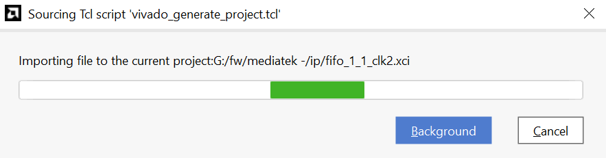\
\&#xNAN;*Wait for Vivado to complete the building of the project files*
## Open Re-customize IP
**How to find and open the `Re-customize IP` window**
After the project is done generating, we will open the `Re-customize IP` window and fill out the information we saved from Telescan [earlier](https://www.simonrak.gay/configuration-space-documentation/home/firmware-guide/telescan/id-s-needed-for-vivado/) `IDs` & `Class Code`
To open the `Re-customize IP` window:
* Click on `> 🔵 pcileech_squirrel_top`\
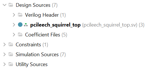
* Click on `> 🔵 i_pcileech_pcie_a7`\
(*The option at the bottom*)\
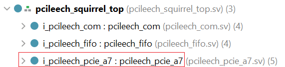
* Double click `🟧 i_pcie_7x_0` to open the `Re-customize IP` window\
\
\&#xNAN;*This will open the `Re-customize IP` window*
## Change ID's & Class Code in Re-customize IP
**Adding ID's & Class Code in `Re-customize IP`**
Inside `Re-customize IP` on the top :
* Click on the tab `IDs`\

* Change these values to what we saved [earlier](https://www.simonrak.gay/configuration-space-documentation/home/firmware-guide/telescan/id-s-needed-for-vivado/):
* `Vendor ID`
* `Device ID`
* `Revision ID`
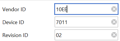
\
(*Can be found in Telescan, at the top of the* [*header*](https://www.simonrak.gay/configuration-space-documentation/home/firmware-guide/telescan/id-s-needed-for-vivado/))
***
**Filling in the `Class Code`**
Still inside the IDs tab, look further down to see `Class Code`
* `Class Code` is filled out from up to down/left to right
* *(explanation below)*
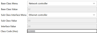
* If our `Class Code` is as below, it will be:
* `Base Class Value` -> `01`
* `Sub Class Value` -> `08`
* `Interface Value` -> `02`

## Save Changes in Re-customize IP
**Leave `Re-customize IP` and generate**
To close the `Re-customize IP` window:
* Click 
* A new window will appear (`Generate Output Products`)
* Select `Global`¹
* And click `Generate`²\
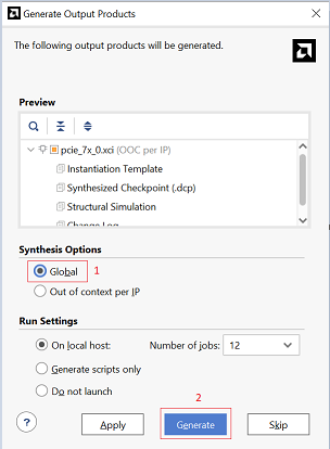
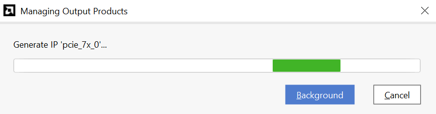
* Wait for the generation to finish\
* Then click `OK`\

## Lock the Core
**Locking the core**
Now we will lock the core to prevent values from overwriting, it also allows us to make some manual changes not available in the Vivado GUI
* At the bottom of the screen, click `Tcl Console`\
\
\&#xNAN;*(If you can't see it, click the search box at the top `Quick Access` and search for `Tcl Console`)*
* Paste `set_property is_managed false [get_files pcie_7x_0.xci]` into the `Tcl Console` and press enter
* This message will be displayed in the `Tcl Console` window:\
\
\&#xNAN;*(The core is now locked)*
* Click on `> pcie_7x_0 : pcie:7x_0`\
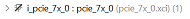
* Double click `> 🔵 inst: pcie_7x_0_core_top (pcie_7x_0_core_top.v)`\

* This will open up a new window to the right\

## Change Values in core\_top.v
**The last step**
This is the last step before we can generate the firmware, we will use the `BAR sizing` and `Max_Payload_Size_Supported` we saved from earlier.
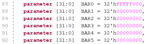
* Go to line 87 to 92 and fill in the `BAR sizings` from [earlier](https://www.simonrak.gay/configuration-space-documentation/home/firmware-guide/telescan/bar-sizing/)
* Fill in the `BARs` you have, leave the others as `00000000`
\
\&#xNAN;*(Only remove the pink text)*
* Go to line 125 and 126 and change it to `0A`
* `EXT_CFG_CAP_PTR = 6'h2A,` -> `EXT_CFG_CAP_PTR = 6'h0A,`
* `EXT_CFG_XP_CAP_PTR = 10'h043,` -> `EXT_CFG_XP_CAP_PTR = 10'h0A,`

\
\&#xNAN;*(¹This moves the starting position of the shadow configuration*)
* Go to line 384 and set `MPS_FORCE` to `TRUE`
* Change `MPS_FORCE = "FALSE",` -> `MPS_FORCE = "TRUE",`

* Go to line 1635 and change the the pink `0` to the same as mentioned [earlier](https://www.simonrak.gay/configuration-space-documentation/home/firmware-guide/telescan/max-payload-size-supported/) \
\&#xNAN;*(In my case it was `010`)*
***
{% hint style="warning" %}
Note
¹*We moved the starting position of the shadow configuration to start after the `BARs` , this will let the core generate the `BARs` instead of the `shadow configuration`*\
\*If we let the `shadow configuration` generate them, it will cause `illegal vendor ID's`
{% endhint %}
## Generate the Firmware
**Generate the firmware**
Now we're finally ready to generate our firmware.
* To the left in the Vivado GUI `PROGRAM AND DEBUG`\
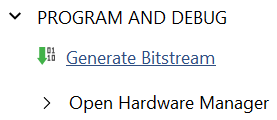
* We click `Generate Bitstream`\

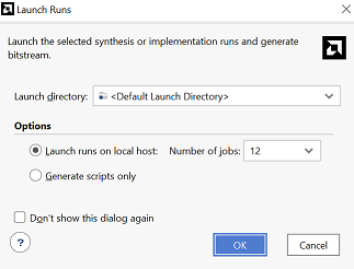
* This will open a window called `Launch Runs`
* Depending on your PC, you can change `Number of jobs`
\
\&#xNAN;*(I have `32 GB` RAM and a `Ryzen 5800x` , 12 `jobs` maxes out my RAM)*
* Click  and wait for the firmware to generate
* A message box will appear after 10-30 minutes, telling us that the build was completed
* The firmware can be found in:\
`/pcileech_squirrel/pcileech_squirrel.runs/impl_1/`
* Named:\
`pcileech_squirrel_top.bin`
*example:*\
`C:/pcileech_squirrel/pcileech_squirrel.runs/impl_1/pcileech_squirrel_top.bin`
---
# Agent Instructions: Querying This Documentation
If you need additional information that is not directly available in this page, you can query the documentation dynamically by asking a question.
Perform an HTTP GET request on the current page URL with the `ask` query parameter:
```
GET https://josiahs-organization-1.gitbook.io/coldpulse-club/getting-started/quickstart.md?ask=
```
The question should be specific, self-contained, and written in natural language.
The response will contain a direct answer to the question and relevant excerpts and sources from the documentation.
Use this mechanism when the answer is not explicitly present in the current page, you need clarification or additional context, or you want to retrieve related documentation sections.